Hardware Ports
Port Layout
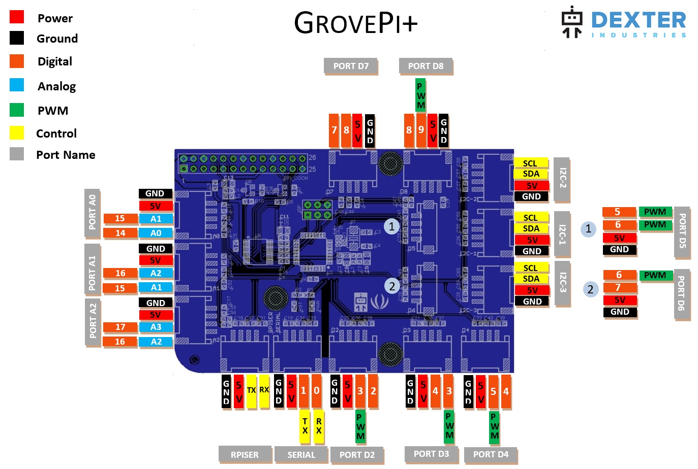
The GrovePi+ has multiple types of ports:
-
Analog ports - A0, A1, A2 - with these ports you can read the voltage output of sensors. In this diagram, these ports are coloured in blue. When using the ports with our API, only use integers to designate the port of your choice such as
0,1or2. -
Digital ports - D2, D3, D4, D5, D6, D7 ,D8 - with these ports you can read and write digital values of 1 or 0. In the above diagram, these ports are coloured in orange. When using the ports with our API, only use integers to designate the port of your choice such as
2,3...8. -
PWM port - 3, 5, 6, 9 - with these ports you can set a specific voltage output between 0V and 5V by using the concept of duty cycle / PWN / PPM.
-
I2C ports - which are coloured in yellow and have the SDA & SCL acronyms written. The master of this connection is the Raspberry Pi.
-
Serial ports - which are found in the bottom-left corner of the above diagram. SERIAL port is the GrovePi's port whereas RPISER is a bypass to the Raspberry Pi's port, which has a level converter implemented to accept 5V signals.
Numbering System
Most of the sensors/actuators that we support have the signal line on the outwards of the grove port. For instance, the Grove LED has the signal line on the edge of the grove port which corresponds to port number 4 on port name D4, so for us this was the reason why the port names we have given actually depend on where the signal lines mostly reside.
Looking at a typical grove cable that comes with any GrovePi kit, the signal line is generally the yellow wire and the white wire is left unused. As you might have guessed, the yellow wire is the outermost wire of the grove cable.